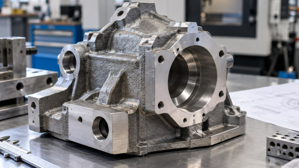
Engineers often discover too late that a cast part looks fine on paper but is difficult to machine without rework. Incomplete cleanup on sealing faces, bores that never center properly, or unexpected movement during finish cuts usually trace back to early decisions in the drawing process. Good castability and good machinability are closely connected. The geometry approved for tooling determines how metal flows, cools, and varies, and those conditions must align with the datum scheme, machining allowance, and tolerance stack. This article focuses on the early decisions that make downstream machining more predictable, helping fixtures clamp once, tools cut once, and inspection reports pass the first time.
Map Critical Surfaces Before You Start the Casting Drawing
Start by separating functional surfaces into two categories: features that must be machined, such as bearing bores, gasketed faces, and reference pads, and features that can remain as cast, such as bosses used only for handling. Identify the primary, secondary, and tertiary datums with the machining setup in mind, then apply geometric tolerances to those datums rather than arbitrary model surfaces. Many casting design guides, including resources from suppliers such as BMF Industrial, emphasize that the machining plan should guide the drawing rather than being considered after the casting geometry is complete.
Consider a pump housing. The impeller bore must remain concentric with a mounting register, while the gasket face must be flat enough to seal without excessively compressing the gasket. If you define the machined register as Datum A, the bore as Datum B, and a bolt slot as Datum C, you can reference a stable setup for coaxiality and flatness requirements. Deciding these things before finalizing the casting model also lets you position pads, ribs, and draft features to support where clamps and locators will contact the part.
Control Cooling With Wall Thickness, Fillets, and the Parting Line
Uneven section thickness can create serious machinability problems. Thick bosses connected to thin ribs can form hot spots that cool slowly and concentrate shrinkage porosity just beneath surfaces later machined. Aim for gradual transitions by using generous fillet radii and consistent wall thickness wherever the design allows. Position the parting line so gravity supports filling and feeding of heavier sections and so any mismatch does not interfere with functional surfaces. Gating and riser locations should support the areas that freeze last, rather than being placed where they are most cosmetically convenient.
A common mistake is adding a thin rib matrix to a large bearing saddle to reduce weight. The saddle remains hot longer, while the ribs freeze first, allowing porosity to develop where a clean bore is required after machining. Correcting the problem may involve thickening the ribs near the saddle, adding a cored relief to create more even mass distribution, or repositioning a riser so it feeds the saddle directly. If the parting line currently crosses a sealing face, moving it to a noncritical wall can reduce mismatch and limit unnecessary stock removal during machining.
Set Realistic Machining Allowance and Surface Finish Targets
Machining allowance, or stock, must account for as-cast surface roughness, mold shift, draft, and any dimensional movement expected after heat treatment. Sand castings generally require more stock than investment castings because their mold surfaces are rougher and dimensional variation is greater. Too little stock can leave islands of uncut material on a flange or produce a bore that barely cleans up and falls outside tolerance. Too much stock increases machining time, accelerates tool wear, and may release residual stresses that cause the part to move during cutting. Specify cast surface finishes where appropriate, and reserve machined finish requirements for functional areas, using Ra or comparable measurements only where necessary.
Consider a gearbox cover with two parallel mounting pads. The stock on each pad should exceed the worst expected mismatch at the parting line while still allowing both pads to be finished in one setup without the tool bottoming out. If the cover will be normalized or stress relieved, schedule that thermal treatment before final machining. Heat treatment can alter hardness and microstructure, affecting tool life and potentially shifting dimensions slightly. Clearly stating the process sequence on the drawing reduces surprises when you inspect the first part on the CMM.
Build a Datum Scheme That Respects As-Cast Variability
Datums established on rough or tapered walls are unreliable because draft can cause dimensions and angles to vary across the surface height. Where possible, define at least the primary datum on a machined surface that will be flat and square. Use machined bores, slots, or pads for secondary and tertiary datums to control rotation and location. If an as-cast surface must be used as a datum, define specific gage points on the drawing so inspection personnel know exactly where to make contact. This approach reduces variability from core shift, flash removal, and parting-line mismatch, all of which can alter as-cast geometry in ways a CMM program cannot simply average out.
GD&T requirements should reflect how the part will actually be clamped and machined. For example, the true position of a bolt circle relative to a machined mounting face (Datum A) and a finished bore (Datum B) should mirror the machining setup. Avoid datum schemes that span multiple surfaces with different draft directions, and avoid choosing a datum surface that loses most of its area during machining. If stock variation is expected, consider allowing partial cleanup on nonfunctional faces, and identify critical quality features with inspection plans that match their risk level.
Verify Early: Sample Inspection, Porosity Checks, and Tool Tuning
First article evaluation lets you compare design intent with actual casting and machining results. Begin with a complete CMM inspection of machined features and critical as-cast dimensions to confirm the datum structure behaves as expected. Add nondestructive testing where failure would be costly. Radiography or CT scanning can identify internal shrinkage in thick junctions, magnetic particle or dye penetrant testing can reveal surface cracks, and hardness checks after heat treatment can confirm machinability targets. For ductile iron components, nodularity and the ferrite-to-pearlite balance influence both mechanical strength and tool wear, so a microstructure coupon may also be useful when the application is sensitive.
Expect some adjustments during development. You may need to move a gate to reduce turbulence and gas porosity in a corner, add a riser to improve feeding of a heavy boss, or modify a core print to reduce core shift that is moving holes out of position. On the machining side, changing a fixture to add a third locator near a thin flange can reduce chatter and improve parallelism. Record these changes in the tooling documentation and update the casting drawing when geometry has been intentionally modified. When casting features and machining strategy support each other, cleanup failures become less frequent, machining cycles become shorter, and inspection results become more consistent across production.